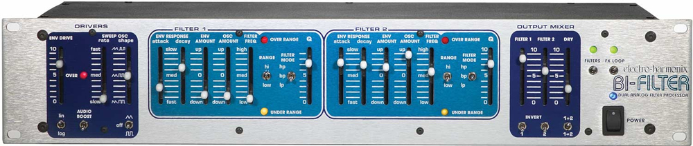
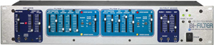
Rack Mount Professional Envelope Follower
Item # 27101
Retail Price
$628.35
Sale Price!
$471.30
Buy Today and Save $157.05 (25% from Retail)
We're sorry, this product is no longer available.

Analog, dual envelope follower utilizing multimode filters and a myriad of state-of-the-art features. There is NOTHING on the market that can match its tone.
The Bi-Filter is the most articulate and wildly flexible filter ever built. Earth Shaking bottom and transparent highs come from. extensive modulation routings combined with multi-mode analog filters (LP, BP, HP with two selectable ranges), which give the user a sound that can only come from a true analog design. Real time control of EVERY parameter is available from the front panel making the Bi-Filter a performer, producer or remixer's dream tool. From subtle to over the top nasty, the Bi-Filter is all about amazing sound.
CONTROLS
Env Drive Controls the envelope follower sensitivity to the input signal. Generally set it so the red OVER LED blinks on the loudest notes, but all settings produce interesting effects. This is not an all or nothing fader. Different locations on the slider produce different results.
Sweep Osc Rate (slow-med-fast) Controls the Low-Frequency sweep oscillator (LFO) rate.
Sweep Osc Shape Slider Changes the LFO waveform duty cycle from 50% in the center position to 10% or 90% at the top or bottom positions. The Shape Slider can be used to change the shape of a triangle wave to a rising sawtooth wave (in the top position) or falling sawtooth wave (in the bottom position). When in square wave mode, the Shape Slider controls the length of the pulse width, from short (in the top position) to long (in the bottom position).
Sweep Osc Shape Switch Switches the LFO waveform from Triangle wave in the top position, to Square wave in the bottom position, to completely Off in the middle position.
Lin/Log Provides different dynamic response to the input signal.
The LOG position produces consistent envelope tracking no matter how soft or aggressive your input signal is.
The LIN position produces an envelope that follows the full dynamic range of the input signal.
0 0
Audio Boost In the DOWN (OFF) position, the audio signal into the filters is set at unity gain. In the UP (ON) position, the audio signal into the filters is amplified according to the setting of the ENV DRIVE slider.
Filter 1/2 Attack Controls the time response of the rising or "attack" portion of the envelope. When the slider is in the FAST (DOWN) position, the envelope will rise with nearly the same attack as your instrument. When in the SLOW (UP) position, the envelope will rise slowly compared to the attack of your instrument. The range of the attack time is approximately 5 milliseconds to 1.5 seconds.
Filter 1/2 Decay Controls the time response of the falling or "decay" portion of the signal envelope. When the slider is in the FAST (DOWN) position, the envelope will fall with nearly the same decay as your instrument. When in the SLOW (UP) position, the envelope will fall slowly compared to the decay of your instrument. The range of the decay time is approximately 10 milliseconds to 1.5 seconds.
Filter 1/2 Env Amount Controls the amount and direction that the filter is swept by the envelope follower. In the 0 (CENTER) position, the envelope follower does not affect the filter. In the UP direction, the envelope sweeps the filter's frequency up from the frequency set by the FILTER FREQ slider. In the DOWN direction, the envelope sweeps the filter's frequency down from the frequency set by the FILTER FREQ slider. The amount of sweep is continuously variable depending on the control settings.
NOTE: sweeping one of the filters UP and the other filter DOWN results in an "out of phase" complementary drive.
Filter 1/2 Osc Amount Controls the amount and direction of filter sweep by the SWEEP OSC (LFO). In the 0 (center) position, the LFO does not affect the filter. For both the UP and DOWN directions of the slider, the LFO sweeps the filter's frequency around the frequency set by the FILTER FREQ slider. In other words, the FILTER FREQ slider will set the center frequency and the LFO will sweep the filter above and below that center. So to sweep the entire frequency range, set the FILTER FREQ slider to MED (the center position) and set the OSC AMOUNT slider to either the maximum UP or DOWN positions. The difference between the UP and DOWN positions is that in the UP position the LFO is non-inverted, in the DOWN position the LFO waveform is inverted. If there is a rising sawtooth set up in the sweep oscillator section, and the OSC AMOUNT slider is set to the DOWN position, the waveform will become a falling sawtooth. NOTE: Setting the OSC AMOUNT of one filter UP and the other filter's OSC AMOUNT DOWN, results in an "out of phase" complementary drive.
Filter 1/2 Filter Freq Sets the filter frequency within its operating range. When no envelope or LFO signals are present, the frequency of the filter is set by the position of this slider. To perform a manual filter sweep, simply push this slider up or down.
Filter 1/2 Range (Hi/Low) Changes the sweep range of the filter:
LOW position gives the filter a sweep range from 150 Hz to 5 kHz.
HI position gives the filter a sweep range from 350 Hz to 12 kHz.
Filter 1/2 Filter Mode (LP/BP/HP) Selects the type of filter characteristic:
LP: Low Pass Mode turns the filter into a Low Pass filter which only passes audio below the cutoff frequency. With no envelope or LFO modulation, the cutoff frequency is set by the FILTER FREQ slider and RANGE switch.
BP: Band Pass Mode turns the filter into a Band Pass filter which only passes audio in the region around the center frequency. With no envelope or LFO modulation, the center frequency is set by the FILTER FREQ slider and the RANGE switch.
HP: High Pass Mode turns the filter into a High Pass filter which only passes audio above the cutoff frequency. With no envelope or LFO modulation, the cutoff frequency is set by the FILTER FREQ slider and RANGE switch.
Filter 1/2 Q Adjusts the filter's quality factor or "Q", also known as resonance. With this slider you have control of the filter's "peak" from a flat roll-off curve to a highly emphasized peak at the cutoff or center frequency. The higher the control setting, the greater the peak of the filter, which will produce a more pronounced filter effect.
Output Filter 1/2 Mixes in the Filter 1/2 output signal.
Output Dry Mixes in the original un-filtered audio signal (AFTER the AUDIO BOOST switch).
Invert 1/2 These switches give the user the ability to invert the signal going into each filter. When listening to one of the filters alone, flipping the Invert switch will have no affect on the sound. If both filters as well as the Dry signal are all mixed together and one or both of the filters have their Invert switch on (along with the right settings for the rest of the sliders), then the user will obtain phase shifter sounds from the Bi-Filter
1+2/1>2 Determines the audio signal path through the filter sections.
1 + 2 Position: Puts the filters in parallel. The signal at the Audio Input jack is fed into both Filter 1 and Filter 2.
1 > 2 Position: Puts the filters in series. The signal at the Audio Input jack is first fed into Filter 1. The output of Filter 1 then goes into the input of Filter 2. The output of Filter 1 will still be available at its mix slider and at its output jack.
Filters Puts the entire Bi-Filter into TRUE BYPASS MODE or EFFECT MODE. When the switch is in the DOWN position, the FILTERS LED, above it, will be off and the entire unit is in true bypass mode. In true bypass mode, the signal into the AUDIO INPUT Jack is connected directly to the MAIN OUTPUT Jack and disconnected from the Bi-Filter circuit. When the switch is in the UP position, the FILTERS LED will be on and the unit is in effect mode. In effect mode, the signal into the AUDIO INPUT Jack is connected to the Bi-Filter circuit. The output of the OUTPUT MIXER section of the Bi-Filter is then connected to the MAIN OUTPUT Jack.
FX Loop Switches the effects send and return loop on or off. When the switch is in the DOWN position, the FX LOOP LED will be off and the external effects loop that is connected to the EFFECTS SEND and EFFECTS RETURN jacks will bypassed. When the switch is in the UP position, the FX LOOP LED will be on and the external effects loop connected to the EFFECTS SEND and EFFECTS RETURN jacks will be engaged. When FX LOOP is on, the external effects loop will be part of the Bi-Filter circuitry. Special Note: When nothing is plugged into the EFFECTS RETURN jack, the FX LOOP Switch will have no function. This switch will only appear to be working when a cable is plugged into the EFFECTS RETURN jack of the Bi-Filter.
IN- AND OUTPUTS
Audio Input Main audio input into the Bi-Filter. Signals from a mixing board or a musical instrument go here.
Effects Send Effects Send is an Output jack that provides a buffered, preamplified version of the signal present at the Audio Input jack. This signal can be used to go into an external effects loop. The output present at this jack is after the Audio BOOST switch on the front panel.
Effects Return Effects Return is an Input jack that accepts the signal from an external effects loop.
NOTE: The Effects Send and Effects Return jacks allow the use of audio effects BEFORE the filter stages. It is therefore possible to put effects on the signal before the filters but still obtain the envelope from the original signal. It is also possible to have one instrument's envelope modulate another instrument: connect one instrument into the Audio Input jack for its envelope and connect another instrument into the Effects Return jack to go through the filters.
Filter 1 Output Audio Output from Filter 1 only. The output is before the Filter 1 MIX slider on the front panel, so the full Filter 1 output will always be available no matter the position of its mixer slider. NOTE: There will be no audio output from this jack when in bypass mode due to the TRUE BYPASS switching of the input signal.
Filter 2 Output Audio Output from Filter 2 only. The output is before the Filter 2 MIX slider on the front panel, so the full Filter 2 output will always be available no matter the position of its mixer slider. NOTE: There will be no audio output from this jack when in bypass mode due to the TRUE BYPASS switching of the input signal.
Main Output Main audio Output for the Bi-Filter. The signal on this jack is the output of the mixer section on the front panel. So there will be a mix of Filter 1, Filter 2 and the Dry input signal coming out of the Main Output jack. When in TRUE BYPASS mode, the DIRECT unmodified instrument signal will be output on this jack.
Envelope 1 CV Output This jack Outputs a Control Voltage of Envelope Follower 1 which modifies Filter 1. The range of this output is 0 - 14 Volts DC.
Envelope 2 CV Output This jack Outputs a Control Voltage of Envelope Follower 2 which modifies Filter 2. The range of this output is 0 - 14 Volts DC.
Filter 1 CV Input Accepts a DC Control Voltage that controls the sweep of Filter 1 through its entire range. This control voltage is ADDED to the control signals from the Envelope Follower, LFO and Filter Frequency slider on the front panel. You may also plug an expression pedal (with a TRS connector) into this input, to control the sweep of the filter with a pedal. The range of this input is 0 - 5 Volts DC. NOTE: You will control the sweep of both Filter 1 and Filter 2 with only this jack if nothing is plugged into the Filter 2 CV Input jack.
Filter 2 CV Input Accepts a DC Control Voltage that controls the sweep of Filter 2 through its entire range. This control voltage is ADDED to the control signals from the Envelope Follower, LFO and Filter Frequency slider on the front panel. You may also plug an expression pedal (with a TRS connector) into this input, to control the sweep of the filter with a pedal. The range of this input is 0 - 5 Volts DC. NOTE: If nothing is plugged into this jack but there is a Control Voltage present in the Filter 1 CV Input jack, it will sweep both filters.
Bypass Footswitch Connects to a 2 channel remote footswitch. The tip of the footswitch's plug controls the Filter Bypass function, which bypasses the entire Bi-Filter. The ring of the footswitch's plug controls the FX LOOP Bypass function. When a footswitch is plugged into this jack, the front panel bypass switches are taken out of the circuit and will not function.
Power Jack This jack accepts the power for the Bi-Filter from the 18VAC/1000mA AC Adapter supplied with the Bi-Filter. Plug the barrel connector from the AC Adapter into this jack.
SPECIFICATIONS
Maximum Input Signal Level 6.3 VRMS (+18 dBV)
Maximum Control Voltage Input Level 5 VDC.
Minimum Control Voltage Input Level 0 VDC.
Maximum Signal Gain (Q Control = 10) 34 dB
Minimum Signal Gain (Q Control = 1) 0 dB
Sensitivity for Full Envelope Sweep (ENV Drive Control = 1): 1.0 VRMS
(ENV Drive Control = 10): 20 mVRMS
Filter Frequency Range LO: 150 Hz to 5 kHz Resonant Frequency
HI: 350 Hz to 12 kHz Resonant Frequency
Frequency Response (Dry Output) Beyond 20 Hz to 20 kHz +- 0.5 dB
Dynamic Range (Measured at output) 105 dB best case
Residual Noise Level -93 dBV worst case
Maximum Undistorted Output +12 dBV worst case
Sweep Oscillator (LFO) Rate Range 0.02 Hz (50 s) to 30 Hz
Envelope Attack Time 5 milliseconds to 1.5 seconds
Envelope Decay Time 10 milliseconds to 1.5 seconds
Envelope Voltage Output 0 to 14 Volts
Related Gear
-
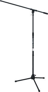
OnStage MS7701B
Item # 1899
Description
$37.95 View Details
Tripod Mic Stand with 33 inch Fixed Boom -
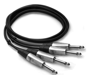
Hosa HPP-010X2 10 ft.
Item # 64099
Description
$25.95 View Details
10-Feet Pro Dual Cable 1/4-Inch TS to Same -

8th Street Music $25 Gift Certificate
Item # g25
Description
$25.00 View Details
Gift Certificate (may be purchased in multiple amounts) -
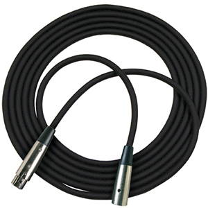
Rapco RM1-25
Item # 2141
Description
$24.95 View Details
25 foot Microphone Cable, XLRM to XLRF -
Rapco G4-10
Item # 2121
Description
$14.49 View Details
10 foot Instrument Cable
 Rack Mount Professional Envelope Follower
MPN #:
UPC #:
Regular price: $628.35
$471.3000
Available from:
8th Street Music
Condition: New
Out of Stock
Rack Mount Professional Envelope Follower
MPN #:
UPC #:
Regular price: $628.35
$471.3000
Available from:
8th Street Music
Condition: New
Out of Stock